RGB dimmer teardown and schematic (no microcontroller)
This must be the first time I've ever referred to the humble 555 as a microcontroller. To be fair, it does have 8 pins and runs at 5V. Maybe a few less transistors though.
Huge processing-power errors aside, this is an interesting and different use of the 555 from normal.
It doesn't use the main output pin, but instead uses the standard configuration to provide a triangular waveform directly from the capacitor.
This is a very retro circuit, but it works well and is fully serviceable at every level, with scope for customisation in terms of PWM frequency and potentiometer range.
The search keywords to find these on eBay are - rgb knob dimmer
If you enjoy these videos you can help support the channel with a dollar for coffee, cookies and random gadgets for disassembly at:-
https://www.patreon.com/bigclive (extra streams and channel interaction)
Or alternatively:-
http://www.bigclive.com/coffee.htm
This also keeps the channel independent of YouTube's advertising algorithms allowing it to be a bit more dangerous and naughty.
#ElectronicsCreators
Видео RGB dimmer teardown and schematic (no microcontroller) канала bigclivedotcom
Показать
Комментарии отсутствуют
Информация о видео
Другие видео канала
 Home bargains solar security light is better than the junk on eBay
 Inside a hover ball
 Big light, but it's PISH! (With schematic)
 Neat "picture" LED night light. With tingle feature.
 Amazon fake 5G safety stickers hazard
 Inside a LIDL rechargeable work light and power bank (with schematic)
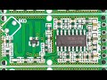 How I get my crisp macro shots with tupper-cam
 eBay vehicle battery disconnectors/isolators
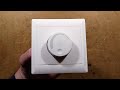 Inside a cheap eBay fan controller (with schematic)
 eBay 3A lithium charger module with schematic
 Farting Ninja teardown (with schematic)
 Inside some stylish wireless switches (including RF schematic)
 Cheap power pack with free lithium cells (USB or solar charging)
 Inside one of the first electronic games.
 Aldi glowing rock (with schematic)
 Hot pink and dangerous (just how we like it)
 Novel rosin vapour short circuit finder
 Perplexing Pink high voltage "thing" (with schematic)
 The unofficial guide to electrocution (and how to avoid it)
 Inside a simple battery tester (with schematic)
 NFC powered flashing fingernail sticker (with schematic)