Turbine Flow Meter Explained | Operation and Calibration
▶ C'mon over to https://realpars.com where you can learn PLC programming faster and easier than you ever thought possible!
=============================
▶ Check out the full blog post over at
https://realpars.com/turbine-flow-meter
=============================
⌚Timestamps:
00:00 - Intro
00:40 - How does a turbine flow meter work?
01:22 - Magnetic pickup sensor
02:02 - Volumetric flowrate
02:54 - The K-Factor
04:51 - A typical field control loop
05:07 - Installation
05:31 - The downsides
06:08 - Where are they used?
=============================
In this video, we’re going to discuss a very common flow measuring device called a Turbine Flow Meter.
We’ll consider the Turbine Flow Meter as a 2-part device:
- the Mechanical component
- the Electrical component.
A Turbine Flow Meter is inserted in a pipe directly in the flow path.
The mechanical part of the Turbine Flow Meter has a turbine rotor placed in the path of a flowing stream.
The only moving part of the Turbine Meter is the mechanical rotor. The rotational speed of the rotor depends upon the flow velocity. The rotor blades are usually made of stainless steel.
As the rotor spins, the passage of each rotor blade past a pickup point will generate an electrical pulse.
The electrical pulses are created in different ways depending upon the rotor blades themselves and the pickup unit characteristics.
In most Turbine Flow Meters, magnets are fitted to the blades, and a magnetic pickup sensor is used to create the pulses.
The higher the rate of flow, the faster the rotor turns and the greater the number of pulses.
The shape and the voltage level of the generated pulses depend entirely upon the type of pickup unit used:
1) The electrical pickup sensing device could be a simple 2-wire passive magnetic pickup producing an AC-type output.
2) The electrical pickup sensing device could be a 3-wire active device such as a Hall Effect sensor that produces cleaner and more uniform square wave pulses.
Fluid Velocity plays a very important role in the operation of a Turbine Flow Meter, but in most applications, a Turbine Flow Meter is used to measure Volumetric Flowrate.
Volumetric Flowrate indicates the volume of fluid that passes a point in a unit period of time.
Volumetric Flowrate is expressed in units such as:
- gallons per minute (GPM)
- cubic meters per second (m³/s)
- cubic feet per second (ft³/s)
When you buy a Turbine Flow Meter it should arrive with a tag or a calibration certificate declaring its K-Factor.
K-Factor will be expressed in terms of the number of pulses produced such as 150 pulses per gallon.
If we have a K-Factor of 3 pulses per gallon, the output frequency at a Volumetric Flowrate of 200 gallons per minute (GPM) is 10 Hertz or 10 pulses per second.
If you are wondering where we derived these values, we’ve included a very handy K-Factor Calculator for you to use: https://bit.ly/3q2brY7
We can connect the Turbine Flow Meter to a PLC Frequency input card. The input frequency now represents the Volumetric Flowrate.
If we are troubleshooting or performing loop calibration, we can use a Calibrator with a variable frequency output to simulate the Turbine Flow Meter.
Typical installation requires 10 pipe diameters upstream of straight pipe and 5 pipe diameters downstream.
The Turbine Meter can only be used in clean, lubricating fluid because suspended particles can easily damage the device.
The turbine rotor must be positioned in the exact center of the flow and laminar flow is critical often requiring straightening vanes.
Even though they are one of the most accurate Volumetric Flow Meters in use today, they do have some downsides.
You will find Turbine Flow Meters in oil and gas including fracking, water and wastewater, chemical, power, food and beverage, aerospace, pharmaceutical, and pulp and paper.
=============================
To learn more, you might want to review our other articles:
How Flow Meters Work https://realpars.com/how-flow-meters-work
What is Sensor Calibration and Why is it important? https://realpars.com/sensor-calibration
What are 2-wire and 4-wire Transmitter Output Loops? https://realpars.com/transmitter-wiring
=============================
Missed our most recent videos? Watch them here:
https://realpars.com/sinking-output/
https://realpars.com/instrument-calibrator
https://realpars.com/plcnext-starterkit
=============================
To stay up to date with our last videos and more lessons, make sure to subscribe to this YouTube channel:
http://bit.ly/realpars
=============================
TWEET THIS VIDEO https://ctt.ac/J4Eao
=============================
Follow us on Facebook: https://www.facebook.com/therealpars
Follow us on Twitter: https://twitter.com/realpars
Follow us on LinkedIn https://www.linkedin.com/company/realpars
Follow us on Instagram https://www.instagram.com/realparsdotcom
#RealPars #Turbine #automationengineer
Видео Turbine Flow Meter Explained | Operation and Calibration канала RealPars
=============================
▶ Check out the full blog post over at
https://realpars.com/turbine-flow-meter
=============================
⌚Timestamps:
00:00 - Intro
00:40 - How does a turbine flow meter work?
01:22 - Magnetic pickup sensor
02:02 - Volumetric flowrate
02:54 - The K-Factor
04:51 - A typical field control loop
05:07 - Installation
05:31 - The downsides
06:08 - Where are they used?
=============================
In this video, we’re going to discuss a very common flow measuring device called a Turbine Flow Meter.
We’ll consider the Turbine Flow Meter as a 2-part device:
- the Mechanical component
- the Electrical component.
A Turbine Flow Meter is inserted in a pipe directly in the flow path.
The mechanical part of the Turbine Flow Meter has a turbine rotor placed in the path of a flowing stream.
The only moving part of the Turbine Meter is the mechanical rotor. The rotational speed of the rotor depends upon the flow velocity. The rotor blades are usually made of stainless steel.
As the rotor spins, the passage of each rotor blade past a pickup point will generate an electrical pulse.
The electrical pulses are created in different ways depending upon the rotor blades themselves and the pickup unit characteristics.
In most Turbine Flow Meters, magnets are fitted to the blades, and a magnetic pickup sensor is used to create the pulses.
The higher the rate of flow, the faster the rotor turns and the greater the number of pulses.
The shape and the voltage level of the generated pulses depend entirely upon the type of pickup unit used:
1) The electrical pickup sensing device could be a simple 2-wire passive magnetic pickup producing an AC-type output.
2) The electrical pickup sensing device could be a 3-wire active device such as a Hall Effect sensor that produces cleaner and more uniform square wave pulses.
Fluid Velocity plays a very important role in the operation of a Turbine Flow Meter, but in most applications, a Turbine Flow Meter is used to measure Volumetric Flowrate.
Volumetric Flowrate indicates the volume of fluid that passes a point in a unit period of time.
Volumetric Flowrate is expressed in units such as:
- gallons per minute (GPM)
- cubic meters per second (m³/s)
- cubic feet per second (ft³/s)
When you buy a Turbine Flow Meter it should arrive with a tag or a calibration certificate declaring its K-Factor.
K-Factor will be expressed in terms of the number of pulses produced such as 150 pulses per gallon.
If we have a K-Factor of 3 pulses per gallon, the output frequency at a Volumetric Flowrate of 200 gallons per minute (GPM) is 10 Hertz or 10 pulses per second.
If you are wondering where we derived these values, we’ve included a very handy K-Factor Calculator for you to use: https://bit.ly/3q2brY7
We can connect the Turbine Flow Meter to a PLC Frequency input card. The input frequency now represents the Volumetric Flowrate.
If we are troubleshooting or performing loop calibration, we can use a Calibrator with a variable frequency output to simulate the Turbine Flow Meter.
Typical installation requires 10 pipe diameters upstream of straight pipe and 5 pipe diameters downstream.
The Turbine Meter can only be used in clean, lubricating fluid because suspended particles can easily damage the device.
The turbine rotor must be positioned in the exact center of the flow and laminar flow is critical often requiring straightening vanes.
Even though they are one of the most accurate Volumetric Flow Meters in use today, they do have some downsides.
You will find Turbine Flow Meters in oil and gas including fracking, water and wastewater, chemical, power, food and beverage, aerospace, pharmaceutical, and pulp and paper.
=============================
To learn more, you might want to review our other articles:
How Flow Meters Work https://realpars.com/how-flow-meters-work
What is Sensor Calibration and Why is it important? https://realpars.com/sensor-calibration
What are 2-wire and 4-wire Transmitter Output Loops? https://realpars.com/transmitter-wiring
=============================
Missed our most recent videos? Watch them here:
https://realpars.com/sinking-output/
https://realpars.com/instrument-calibrator
https://realpars.com/plcnext-starterkit
=============================
To stay up to date with our last videos and more lessons, make sure to subscribe to this YouTube channel:
http://bit.ly/realpars
=============================
TWEET THIS VIDEO https://ctt.ac/J4Eao
=============================
Follow us on Facebook: https://www.facebook.com/therealpars
Follow us on Twitter: https://twitter.com/realpars
Follow us on LinkedIn https://www.linkedin.com/company/realpars
Follow us on Instagram https://www.instagram.com/realparsdotcom
#RealPars #Turbine #automationengineer
Видео Turbine Flow Meter Explained | Operation and Calibration канала RealPars
Показать
Комментарии отсутствуют
Информация о видео
Другие видео канала
 What is a Vibration Sensor?
 The Coriolis Flow Measuring Principle
 How to Tune a PID Controller
 Magnetic Flow Meter Technology Introduction
 What is the Difference Between PLC and DCS?
 Video positive displacement meters
 Differential Pressure Transmitter Explained
 The Electromagnetic Flow Measuring Principle
 Coriolis Flow Meter Theory of Operation
 Pt100 Sensor Explained | Working Principles
 How Flow Meters Work
 Sinking and Sourcing PLC Outputs Explained
 What is a Gas Turbine? (For beginners)
 How to Measure Flow Rate with a DP Transmitter
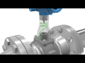 Introduction to Vortex Flow Meter Technology
 PID Controller Explained
 The Vortex Flow Measuring Principle
 What is a Servo Motor and How it Works?
 What is a Level Sensor?