#1 Tutorial: Making A Ribbon Cable
Quick vid of Making a Ribbon Cable with Two Connectors.
Done in FreeCAD but, general approach is valid for all CAD programs.
Play SPEED Control: Click the Cog and select desired speed
#1 Tutorial: Shows the process of ‘Making’ the FreeCad model (A Ribbon Cable) and Exporting it without using StepUp plugin.
https://www.youtube.com/watch?v=oxPRGyvBuTU&feature=youtu.be
#2 Tutorial: Shows a completed Jumper Wire and it’s implementation into KiCad. (same process as for making the Ribbon Cable. This time, the model contains Two Bodies).
https://www.youtube.com/watch?v=zMlu-rxtYSQ&feature=youtu.be
#3 Tutorial: Shows a more complex model - a Coffee Cup with two contact pins (on cup bottom). Shows it’s implementation in KiCad.
https://www.youtube.com/watch?v=88NsRVC-Mo8
#4 Tutorial: Start To Finish - Making A Cable Assembly & Footprint
https://www.youtube.com/watch?v=szj5xV5UF9Q
------------------------------------------------------
* Tutorial #1 General Process: *
1) Create a Cross-Section of the Cable
2) Create a Path to Sweep the Cross-Section
3) Create Connectors on both ends of the cable
4) Color as desired
5) Export
Intended use is for a KiCad Footprint.
Exported .STEP can be done via Export and/or from the StepUp Plugin.
NOTE: You'll need to learn how to make good Sketches without errors (or it won't Sweep). Thus, this video assumes you know how to do that...
I did not fuss with making Actual/Real size Cable or Connectors.
This is Only a Graphic part for a KiCad Footprint. But, you can certainly make a 'Real' cable and connectors, is desired...
Видео #1 Tutorial: Making A Ribbon Cable канала Bruce T
Показать
Комментарии отсутствуют
Информация о видео
Другие видео канала
 DSC Digital Setting Circle For Telescope
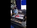 3018 Pro Mill CNC Testing & Info
 Custom PCB for Use in Fritzing
 #1: Tutorial - Making a PCB With Cutouts, For Fritzing
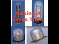 Making Electronic Tubes, Bulbs, LED's... etc
 Tinning Solution - Homemade Tinning Solution for PCB's
 3D-STEP File Coloring
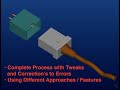 #5 Tutorial: FreeCAD To KiCad - Detailed
 Continuation - Making a Hole in the Box...
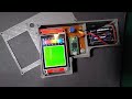 Thermal Camera Using Teensy Arduino
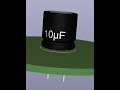 FreeCad - Kicad Capacitor Modeling
 Digital Setting Circles for Telescope
 Kicad Trace Length Plugin
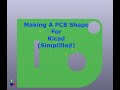 FreeCad To Kicad PCBShape - Simplified
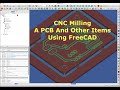 CNC Milling A PCB
 FreeCAD For Kicad PCB Shapes And Cutouts
 Making A KiCad Edge Card Footprint
 PCB Box For Kicad-PCB's
 Making A Cable Assembly & KiCad Footprint - Start to Finish
 HomeMade Tinning-Solution For PCB's