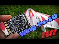
How To Wing FC-10 flight controller setup for planes and flying wings with inav flysky frsky
In this video, we are going to see how the basic setup of the wing-FC 10 flight controller is carried out. This controller is suitable for airplanes and flying wings. It can be found for a price of approximately 23 euros.
We start by soldering a female XT60 connector for the battery. We also solder another male XT60 connector for the ESC. Lastly, we solder the pin tablet.
On this controller, we can connect an FPV camera to the V-in, VCC, and ground holes, which are on the penultimate row of the tablet.
We can also connect a VTX video transmitter using the V-out, battery, ground and TX4 holes.
A fr-sky receiver with smart port can be plugged into the RX3 and SP0 holes. The ground and 5-volt wires are plugged in any available power holes.
We can bind the FlySky FS-IA6B, and FS-x6b receivers, by PPM signal, through channel number one. Simply connect the serial cable to the RX3 hole. The ground and 5-volt wires are plugged in any available power holes. Remember to activate the PPM option on the FlySky transmitter.
If we use a TBS crossfire receiver, we must use the TX5 and RX5 holes. The ground and 5-volt wires are plugged in any available power holes.
We can install a GPS module using the RX2 and TX2 holes. The ground and 5-volt wires are plugged in any available power holes. It is noted that there is a hole for 3.3 volts, and some GPS modules work well with that voltage.
We can also install a buzzer using the BZ plus and BZ minus holes.
There are four ports for servos, each one with the PWM signal, 5 volts and ground holes.
The wires from the ESC are plugged into the first two rows of connectors. Note that all ESC for airplanes have three wires, the one in the middle being a 5-volt power wire. This controller is not powered by the ESC, but directly from the battery. Therefore, the middle wire of the ESC has to be cut. If we use an ESC for drones, it just has two wires, without the 5-volts wire.
We move on to the software configuration. We start by downloading the i-nav configurator and installing the drivers to connect the PC with the flight controller.
For the drivers, we can use the ZADIG software. We can also download the Impulse RC Driver Fixer software. When executing this software, it installs the necessary drivers for the communication of the PC with the controller.
Once the software finishes the operations, we check on the Devices and printers page of the PC that we have a STM32 BOOTLOADER device.
We are going to update the firmware of the flight controller to the latest version available. We need a USB to micro USB type cable capable of data transmission.
We press the bind button, and connect the cable from the flight controller to the PC. We see that the blue light does not blink, so the controller entered into the read-write mode.
The steps to update the firmware are shown.
When using FlySky receivers and frsky receivers, we have to choose the UART 3 as the serial port for the communication between the receiver and the flight controller. For GPS modules, UART 2 is used, and we must change the baud rate to 57,600.
On the contrary, if we use a long-range TBS crossfire receiver, we must choose UART port 5 as the serial port.
We are going to work with a FlySky receiver. Thus, in the i-nav configurator, we must select the channel map as AETER, and the receiver mode as PPM.
In the mixer tab, we must remove one of the engines if our plane is not twin-engine.
As we do not have a GPS installed yet, we have set the failsafe in drop mode. If we set a different mode without having a GPS, we will not be able to arm the plane.
On a day with winds of up to 25 kilometers per hour, we tested the flight modes with acro stabilization, and angle stabilization, and compared them with the behavior of the plane in the manual mode.
It is noted that all trims of the aircraft's control surfaces must be carried out in the i-nav configurator. In the radio transmitter, the settings, end points, channels reversing, mixes and other configuration must be set at factory settings. Therefore, the servo rods must have the right and exact length, so that their neutral position is the one that makes the plane fly in a stable way.
On this controller, the internal voltage regulator is 5 volts and 3 amps. If the amperage of all the connected devices is higher than 3, we should derive some of the 5-volt wires, together with the ground wire, to an external battery equipped with its own voltage regulator. That is, we can power, for example, the signal transmitter and the camera outside the controller. Either we can power all servos outside the controller. This is actually necessary, as we don't have enough 5 volt and ground holes to power all the devices that can be connected simultaneously.
And this is all for now. This project will be continued in a next video. Thank you.
Видео How To Wing FC-10 flight controller setup for planes and flying wings with inav flysky frsky канала Fisica y Quimica Canal
Показать
Комментарии отсутствуют
Информация о видео
13 сентября 2020 г. 16:24:20
00:10:46
Другие видео канала
 Wing FC-10 Тест самого бюджетного полетника для ЛК и самолетов! Это не Матек, но покатит...
 How to setup Wing FC-10 flight controller for GPS flight modes: return to home, hold position INAV
 iNav Mission Control for Fixed Wing ✈️ How to and Demo Autonomous Waypoint Mission 🤖
 HOW-TO Full Autopilot and FPV system on almost any model plane
 Building a Cockpit to Fly RC Planes?? 😱
 Racerstar F405 Wing Nano
 Fixed wing flight controllers: Which to use
 RC Receivers Stabilizers and Flight Controllers - Which One and When?
 Racerstar F405 Deluxe: A cheap GPS flight controller that comes with everything for fixed wing?
 Matek F722 WPX First Look • iNav 2.6 First Look • Flashing Firmware
 HobbyEagle A3-L V2.0 Fixed Wing Stabiliser Setup
 How to INSTALL ANDROID head unit into VAUXHALL OPEL ASTRA H double din car stereo STEP BY STEP
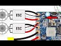 Matek F405-Wing with iNav Being Installed into an Opterra 1.2M
 Prueba XK X450 VTOL 2.4G 6CH EPO 450 mm Envergadura 3D / 6G Modo conmutable Aerobatics RC Avión RTF
 ZOHD Kopilot Lite: Easy stabilisation and RTH for fixed wing
 Setting up FlySky Radio for Airplanes | Dual Rate | Expo | Landing Gear
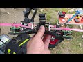 Dron de carreras con bateria 5s. Freestyle. Visto desde fuera. Dron rapido y potente. Acrobacias
 DW Lighting Setup and Maiden
 How To Make Drone With Naze 32
 Easy Flying Wing Setup for Quad Pilots