Inside a nasty high voltage ozone generator PSU. (with schematic)
I had a feeling the circuitry was going to be like this, but in a way it was simpler than expected.
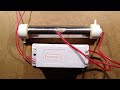
This is a high voltage power supply for running dielectric barrier ozone generators like the inline air tubes and ceramic plate types.
The circuitry is clearly optimised for cost and reliability, at the cost of being quite electrically spiky. It literally shunts capacitors 100/120 times a second.
There's one slight oddity, even for such a simple circuit. I was expecting there to be something like a diac to provide a clean switching pulse to the thyristor. Instead it sees a fairly slow rise via a resistor and capacitor. The gate current on this component is a surprisingly low 200uA.
For those not familiar with thysistors, they are a power switching component that only conducts in one direction like a switchable diode. When a high enough current is flowing in the gate it causes the thyristor to latch on like a switch until the current flowing through it falls below its latching threshold. In this circuit it is being used to dump the charge on a capacitor through the primary of the simple ferrite rod transformer to induce a high voltage on the other secondary.
If you enjoy these videos you can help support the channel with a dollar for coffee, cookies and random gadgets for disassembly at:-
http://www.bigclive.com/coffee.htm
This also keeps the channel independent of YouTube's advertising algorithms allowing it to be a bit more dangerous and naughty.
Видео Inside a nasty high voltage ozone generator PSU. (with schematic) канала bigclivedotcom
Показать
Комментарии отсутствуют
Информация о видео
Другие видео канала
 Inside an airline cold-plasma ozone generator cold-plasma tube.
 LED lamp with tiny 5kV high voltage ion module. (inc schematic)
 Random high voltage eBay "thing"
 Cheap imported "rainproof" power supply (long version).
 How to safely remove hazardous substances from wastewater using ozone
 Shorting out a fully charged cheap lithium jump starter. (It didn't end well.)
 A look inside the notorious EE Power Bar.
 Exploring a popular Japanese air purifier.
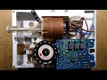 Teardown of a British electric shower that went bang.
 Building a Homemade Bandsaw // Büyük Boy Şerit Testere - Hızar Yapımı
 High Voltage Vacuum Tube Electrolytic Capacitor Discharge Probe / Tool - BG074
 Inside a Pound shop car-USB charger (with schematic)
 How to Make High Voltage Capacitors - Homemade/DIY Capacitors
 Simple Cheap High Current Power Supply From A Microwave Oven Transformer
 Hacking and overclocking a BMW "ioniser". (Not recommended)
 High Voltage Jacob's ladder with Gabriel electrode. (quieter from 2.02)
 Testing for electric match misfire. (bangs and flames)
 How To Make a Homemade Ozone Generator (Air Purifier)
 Industrial ozone Generator DIY
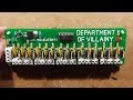 Building the Dept of Villainy LED neon controller.