Wien Bridge Oscillator (using op-amp) Explained
In this video, the design and working principle of the Wein Bridge Oscillator has been explained.
By watching this video, you will learn the following topics.
0:26 Introduction to Wein Bridge Oscillator
2:31 Resonant frequency and the Oscillation criteria for the Wein Bridge Oscillator
5:07 Example: Design of Wein Bridge Oscillator
6:58 Derivation of frequency for the Wein Bridge Oscillator
The Wein Bridge Oscillator:
The Wein Bridge Oscillator is one of the RC oscillators which is used for the generation of sine waves in the range of audio frequency range.
In this Wein Bridge Oscillator, the RC network is used in the feedback for the generation of oscillation. The RC network acts like a notch filter and at only one frequency the phase shift offered by the feedback network is zero. As the feedback network provides the zero degree phase-shift, the amplifier should also provide the zero degree phase shift.
And when it is designed using the op-amp, then op-amp is used in the non-inverting configuration. (So that the [phase shift introduced by the amplifier is zero).
At the resonant frequency, the feedback fraction β is equal to 1/3.
And to sustained oscillation, the gain of the op-amp should be slightly more than 3. (i.e A should be greater than 3)
In Wein Bridge OScillator, the positive feedback is provided to the op-amp through the RC feedback network and there is a negative feedback to the op-amp through non-inverting configuration. It means in Wein bridge oscillator there is both positive and negative feedback.
If resistors R1= R2 and C1= C2 in the circuit then the resonant frequency f= 1/(2π RC)
And to achieve a gain of 3, R4/R3 should be equal to 2.
For practical design, the gain of op-amp should be slightly more than 3. (i.e R4/R3 should be more than 2).
In this video, the working principle of the oscillator is explained and the oscillator is designed for 10 kHz frequency.
And in the latter part of the video, the equation for the Wein Bridge Oscillator has been derived.
This video will be helpful to all the students of science and engineering in understanding the working and design of the Wein Bridge Oscillator.
#WeinBridgeOscillator
Follow me on YouTube:
https://www.youtube.com/allaboutelectronics
Follow me on Facebook:
https://www.facebook.com/ALLABOUTELECRONICS/
Follow me on Instagram:
https://www.instagram.com/all_about.electronics/
Music Credit:
http://www.bensound.com/
Видео Wien Bridge Oscillator (using op-amp) Explained канала ALL ABOUT ELECTRONICS
Показать
Комментарии отсутствуют
Информация о видео
Другие видео канала
 Quiz 33 (Solution)
 Membership Quiz # 6 (Digital Electronics - Combinational Circuits)
 Current Shunt Feedback Amplifier Explained | Feedback Amplifier
 Effect of Propagation Delay on Asynchronous Counter (Ripple Counter) Explained
 What is the Laplace Transform of Trapezoidal Function ?
 Current Series Feedback Amplifier Explained | Feedback Amplifier
 Feedback Topologies in Amplifier Explained | Feedback Amplifier
 Quiz 35 (Solution)
 Membership Quiz # 9(Analog Communication - Amplitude Modulation )
 Applications of Shift Register | Ring Counter and Johnson Counter, PRBS Generator
 Electronics in Space Applications
 Inverse Laplace Transform using Partial Fraction Expansion (Part-2)
 MOSFET - Differential Amplifier (Small Signal Analysis)
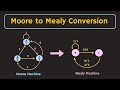 Moore to Mealy Conversion Explained | How to Convert the Moore Machine to Mealy Machine
 What is Thermistor ? Types of Thermistors | Applications of Thermistor Explained
 What is Clock Skew ? The Positive and Negative Clock Skew Explained
 Wired AND Logic Explained | What is Wired Logic in Digital Electronics ?
 SSB Generation Methods : Phase Shift Method and Filter Method Explained
 Op-Amp: What is PSRR (Power Supply Rejection Ratio) ? PSRR Explained
 Voltage Series Feedback Amplifier Explained | Feedback Amplifier
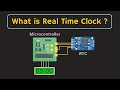 What is Real Time Clock (RTC)? How RTC works? Applications of Real Time Clock