- Популярные видео
- Авто
- Видео-блоги
- ДТП, аварии
- Для маленьких
- Еда, напитки
- Животные
- Закон и право
- Знаменитости
- Игры
- Искусство
- Комедии
- Красота, мода
- Кулинария, рецепты
- Люди
- Мото
- Музыка
- Мультфильмы
- Наука, технологии
- Новости
- Образование
- Политика
- Праздники
- Приколы
- Природа
- Происшествия
- Путешествия
- Развлечения
- Ржач
- Семья
- Сериалы
- Спорт
- Стиль жизни
- ТВ передачи
- Танцы
- Технологии
- Товары
- Ужасы
- Фильмы
- Шоу-бизнес
- Юмор
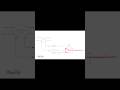
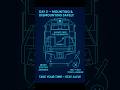
How to Read a Locomotive Electrical Schematic | Understanding Baseline Drawn Conditions
This video explains how locomotive electrical schematics are drawn and how to read them correctly, focusing on the baseline conditions under which the schematic logic is shown.
Locomotive electrical schematics are not drawn under fault conditions and are not showing a running locomotive. They are drawn in a known, standardized state, which allows electricians and technicians to understand circuit logic without guessing.
That baseline drawn condition includes:
• No electricity applied
• Forward direction selected
• Motoring state
• Isolation switch open
• No air pressure
• No water in any tanks
• 60°F ambient temperature
• No oil, water, or fuel pressure
Because the schematic is drawn in this state, interlocks, relays, pressure switches, and temperature-dependent devices appear exactly as they would under these conditions.
If a device would only actuate with air pressure, heat, or electrical power, it will not be shown actuated in the print—because those conditions do not exist in the drawn state.
This approach allows technicians to:
• Read schematics as state-based logic documents
• Mentally apply conditions and predict circuit behavior
• Avoid misinterpreting contacts as failed or wired incorrectly
• Troubleshoot systematically instead of guessing
This training is intended for locomotive electricians, signal and PTC technicians, apprentices, and anyone learning to properly interpret railroad electrical prints used on modern and legacy locomotives.
Change the condition — and the logic changes.
Видео How to Read a Locomotive Electrical Schematic | Understanding Baseline Drawn Conditions канала PTCS
Комментарии отсутствуют
Информация о видео
22 января 2026 г. 8:27:12
00:01:05
Другие видео канала