- Популярные видео
- Авто
- Видео-блоги
- ДТП, аварии
- Для маленьких
- Еда, напитки
- Животные
- Закон и право
- Знаменитости
- Игры
- Искусство
- Комедии
- Красота, мода
- Кулинария, рецепты
- Люди
- Мото
- Музыка
- Мультфильмы
- Наука, технологии
- Новости
- Образование
- Политика
- Праздники
- Приколы
- Природа
- Происшествия
- Путешествия
- Развлечения
- Ржач
- Семья
- Сериалы
- Спорт
- Стиль жизни
- ТВ передачи
- Танцы
- Технологии
- Товары
- Ужасы
- Фильмы
- Шоу-бизнес
- Юмор
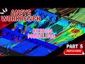
TOLERANCES IN MANUFACTURING | GD&T | PART 5
TOLERANCES IN MANUFACTURING | GD&T | PART 5
GD&T is a symbolic language used in engineering drawings to describe the size, form, orientation, and location of features on a part, along with their allowable variation (tolerance). Part 5 likely focuses on advanced tolerance types or practical applications.
Here’s a structured overview:
1. Recap of GD&T Basics
GD&T Symbols define geometric controls:
Form – Straightness, Flatness, Circularity, Cylindricity
Orientation – Perpendicularity, Parallelism, Angularity
Location – Position, Concentricity, Symmetry
Profile – Line profile, Surface profile
Runout – Circular runout, Total runout
Tolerance defines the permissible variation of a feature.
2. Types of Tolerances in Manufacturing
GD&T tolerances are functional, meaning they ensure the part works as intended rather than just fitting a dimension. Common categories:
a) Form Tolerances
Control shape of a feature without reference to another feature.
Examples:
Straightness – a line must be straight within a tolerance zone.
Flatness – a surface must lie between two parallel planes.
Circularity – a circular feature must lie between two concentric circles.
b) Orientation Tolerances
Control tilt or angle of a feature relative to another feature.
Examples:
Perpendicularity – must be 90° relative to a datum.
Parallelism – must be parallel to a datum surface.
Angularity – must maintain a specific angle.
c) Location Tolerances
Control position relative to a datum.
Examples:
Position – the center of a hole must be within a tolerance zone.
Concentricity – center axis of a feature must align with a datum axis.
Symmetry – feature must be symmetric about a datum plane.
d) Profile Tolerances
Control complex surface shapes.
Examples:
Profile of a line – tolerance along a curve or edge.
Profile of a surface – tolerance across an entire surface.
e) Runout Tolerances
Control rotation-related errors.
Examples:
Circular runout – tolerance for a single cross-section of a rotating feature.
Total runout – tolerance for the entire surface of a rotating feature.
3. Tolerance Values and Zones
Tolerances are applied as zones in which the feature must lie.
Common zones:
Straightness/Flatness – two parallel lines or planes.
Position – cylindrical or rectangular zones around a feature.
Profile – 3D surface zone.
4. Practical GD&T Application Tips
Always define datums first – they are reference features.
Use tight tolerances only where function requires them.
Avoid redundant tolerances – they can confuse manufacturing.
Combine form + orientation tolerances when needed (e.g., a hole must be circular and perpendicular).
GD&T tolerances
Geometric dimensioning and tolerancing
Manufacturing tolerances
Engineering tolerances
Part design tolerances
Form tolerances
Orientation tolerances
Location tolerances
Profile tolerances
Runout tolerances
Precision engineering
Mechanical engineering drawing
Datum features
Tolerance zones
CNC manufacturing tolerances
#GDandT
#ManufacturingTolerances
#EngineeringDrawing
#PrecisionEngineering
#MechanicalDesign
#EngineeringEducation
#CNCManufacturing
#FormTolerance
#OrientationTolerance
#LocationTolerance
#ProfileTolerance
#RunoutTolerance
#PartDesign
#EngineeringTips
#ManufacturingProcesses
GD&T tutorial
GD&T for beginners
Tolerances in manufacturing
Part 5 GD&T series
Engineering drawing tutorial
Mechanical tolerancing
CNC machining tolerances
Datum and tolerance zones
Form and orientation controls
Manufacturing quality control
Видео TOLERANCES IN MANUFACTURING | GD&T | PART 5 канала Learning VIDEOS
GD&T Tolerances Explained | Manufacturing Part 5 TOLERANCES IN MANUFACTURING | GD&T | PART 5 GD&T Tolerances in Manufacturing | Full Part 5 Tutorial Master GD&T Tolerances for Manufacturing | Part 5 Tolerances in GD&T – Part 5: Form Orientation Location Understanding GD&T Tolerances in Manufacturing | Part 5 GD&T in Action: Manufacturing Tolerances Explained – Part 5 Manufacturing Tolerances GD&T Part 5 GD&T Part 5 – Tolerances Overview Engineering GD&T Tolerances Explained
Комментарии отсутствуют
Информация о видео
5 апреля 2026 г. 11:40:25
00:02:29
Другие видео канала